|
The
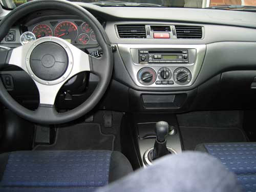
project car that we will be using for the installation
is a Mitsubishi Lancer Evolution. The great
thing about the Hallman Evolution Boost Controller
kit is that you can adjust your boost from inside
the car. This is really great for setting your
initial boost for the very first time. Now you
can set your boost within a minute or two and
never stop the car. No more looking for a place
to pull over and having to get out and pop the
hood to make adjustments.
Installing this kit is not hard, but it does
take more time than installing your standard
under the hood boost controller. If you have
3 - 6 hours (depending on the car) you can end
up with an excellent installation. For example,
the Mitsubishi Evolution installation requires
more dissasembly than installing this kit in
a Eagle Talon. A little extra time spent now
will mean having a trick and professional install.
Well, lets get to it.
Step
1: Interior, Adjustment Knob Installation
|
|
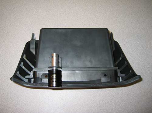
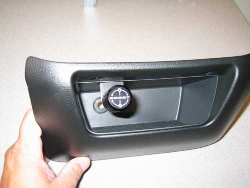
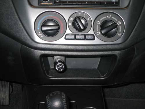
- We
decided to mount the adjustment knob inside
the compartment located below the temperature
controls. This will be a good spot that will
be aesthetically pleasing and also easy to
reach.
|
|
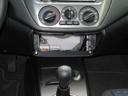
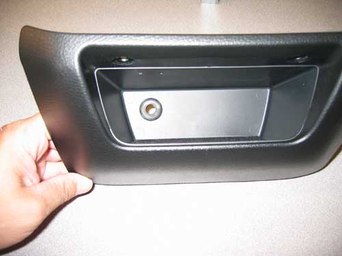
- First
you must remove the compartment so that you
can work on mounting the adjustment knob
|
|
- The
compartment is easily removed by taking out
the two phillips head screws in the top of
the compartment.
Step
2: Interior, Mounting the Adjustment Knob
|
|
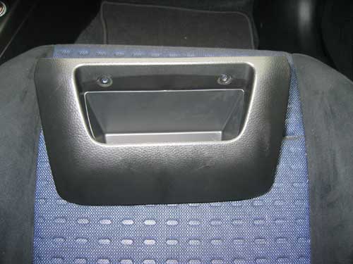
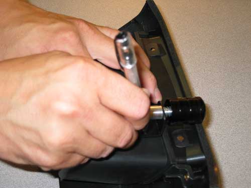
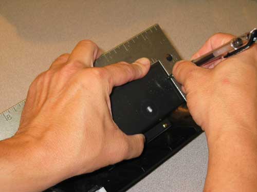
- First,
lay out the knob where you would like it to
be located, be sure that it does not interfere
with being able to replace the screws when
reinstalling the compartment.
|
|
- Next,
mark you holes with a pen
|
|
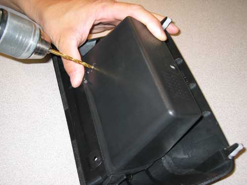
- Drill
your two holes for the mounting bracket with
a 3/16th inch drill bit.
|
|
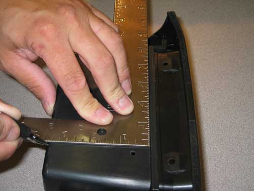
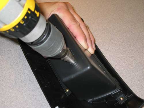
- We
will need to drill a hole in the back of the
compartment for the cable to come through.
We used a square to center our hole so that
it will line up with the adjustment knob.
|
|
- We
used the square to extend the line down and
mark our hole on the back side of the compartment.
|
|
- Drill
a 5/8th's inch hole in the back of the compartment.
|
|
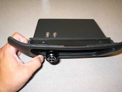
- Install
a grommet with a 3/8th's inch ID hole in it.
This will fit and support the cable very nicely.
|
|
- Mount
the adjustment knob bracket using very short
machine screws and nuts.
|
|
- Here
is your finished product.
Step
3: Interior, Drilling the Firewall
|
|
|
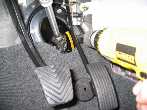
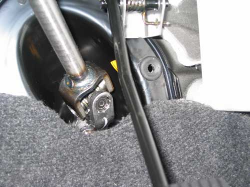
This
step should take some thought and serious measuring.
Measure twice - Drill once! Look at both sides
of the firewall, you do not want to drill through
a brake line, AC line, or Heater core hose.
On the Mitsubishi Evo about the only option
that you have to be safe on both sides of the
firewall is to drill here. (Click on picture
for a close-up)
|
|
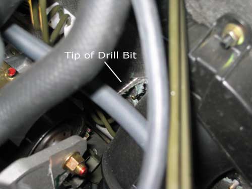
| You
can see where the drill bit comes through the
firewall on the engine compartment side. |
|
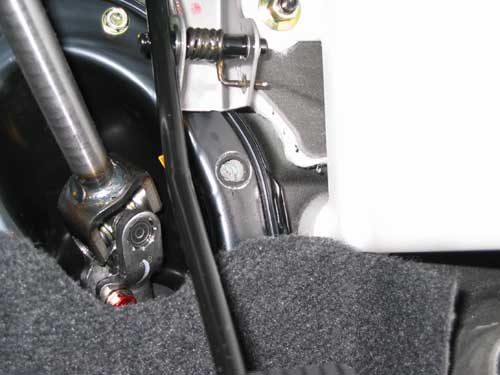
- Here
you can see the hole that we drilled.
|
|
- We
installed another 3/8th's ID grommet to protect
the cable and seal the hole where it will
pass through the firewall.
Step
4: Exterior / Interior, installing the cable
|
|
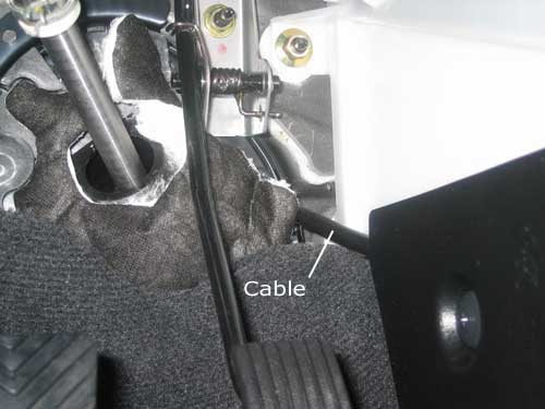
- It
will be much easier to install the cable through
the firewall if the Strut Tower Brace is removed.
|
|
- After
the cable is installed it can be routed behind
the kick plate and through the dash.
|
|
- Next,
route the cable through the back of the compartment
and attach it to the knob assembly, then the
compartment can be mounted back into the dash
of the car.
|
|
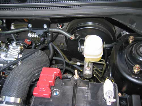
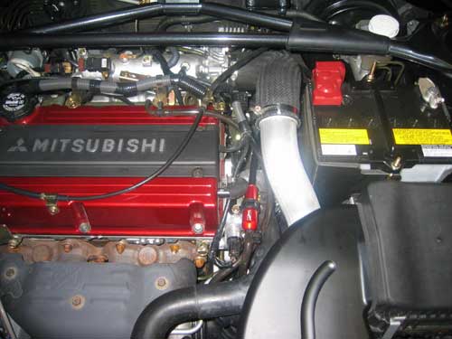
- We
decided to mount the valve to the top of the
cam position sensor on the side of the valve
cover. To do this we had to remove the hard
line from the bracket that feed vacuum to
the BOV. Instead we installed a soft line
from hard line off of the intake manifold
to the BOV. This allowed us to mount the valve
to the cam sensor. (click on the picture for
a close-up).
Step
5: Exterior, Installing the Hallman valve
|

|
- We
recommend taking the boost control solenoid
out of the system when installing a boost
controller. This is located under the factory
airbox in the Evo. We suggest leaving the
solenoid plugged into the factory wiring harness
but using a vacuum cap to plug off the input
of the solenoid (click on the picture for
a close-up).
|
|
- Now
it is time to hook up the vacuum lines from
the boost source and the wastegate actuator
to the Hallman boost control valve. It is
much easier to access the boost source and
wastegate actuator if you remove the fan from
the radiator. This is a bit difficult to get
out of the engine bay. You have to remove
a portion of the upper intercooler pipe to
have enough room to get the fan out of the
car. Make sure that you have enough room to
pull it out so that you do not damage the
radiator.
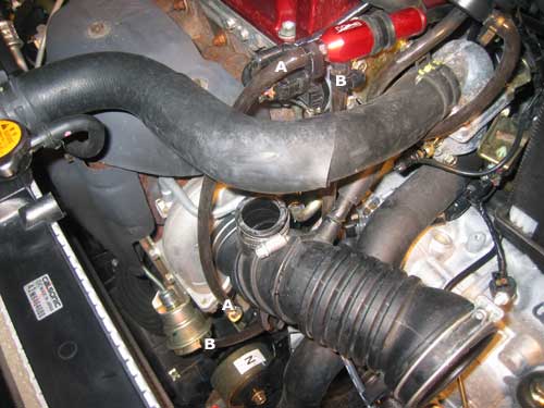
- The
picture is labeled so that you can see where
the lines should be hooked up so that the
boost controller functions properly. The line
that is labeled "A" is your boost
source line and needs to be connected to the
input of the Hallman valve. The line that
is labeled "B" is your wastegate
actuator line and needs to be connected to
the output of the Hallman valve. (Click on
the picture for a close-up).
- At
this point you are ready to put the car back
together. Once you have double checked everything
it will be time to set the boost. Start with
the Hallman boost control valve adjusted to
stock boost. make sure that the knob it turned
all of the way counter-clockwise. Drive the
car and monitor your boost with an aftermarket
boost gauge. Start turning the knob clockwise
a whole turn. Check the boost again and repeat
the above steps until the desired level is
reached.
|